Day 23
Programmable Light-up Leg Warmers are a great way to show off your style when walking around during the Christmas season. Incorporating a switch and a button so that the possibilities are endless when it comes to changing what the leg warmers will look like. I love to walk around, feeling confident. Putting on my boots and Programmable Light-up Leg Warmers makes me want to strut and dance around all night. Let’s get building!!!
Gather your Materials
- Heavy cotton
- Light cotton
- Fur Fabric
- Zipper (X2)
- Elastic
- Bias tape
- Individually addressable LED’s
- Wire
- Button
- Switch
- Seeedunio Board (X2)
- Computer
- Soldering Iron and Solder
- Sewing machine
- Third arm
- Dremel Cutting and sanding
- PCB board
Designing the Programmable Light-up Leg Warmers

There are many different ways to make insert LED’s into leg warmers. For instance, you can grab a string of lights and sew them in between the two-layer and have an on/off switch already attached to the LED’s. Another way is similar to how we incorporated LED’s into the LIght-up Santa Hat. However, for these Programmable Light-up Leg Warmers, I wanted control of what the LED would do. I designed the leg warmers with three rows of lights. Each row would be connected to a different port so that eventually they could be all controlled separately. Today I am going to set the code to do all the same program. However, this makes the Leg Warmers more versatile in the future.
Sewing the Programmable Light-up Leg Warmers
Making the Pattern and Cutting it out
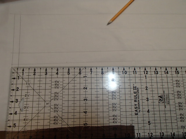
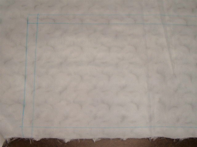
Draw one square that is 17.5 wide by 2.25 tall. These will mark your stitching lines. On the short sides, add .5 inch of seam allowance. On the top, add 1.5 seam allowance, and on the bottom, add 1-inch seam allowance. Draw a second square that is 17.5 wide by 3.75 tall. Again on the short side, add .5 inch seam allowance. On the top, add 1 inch, and on the bottom, add half an inch. These two pieces will combine to create the lining of the Leg warmer.
Cut out a piece of fur that is 17.5 inches wide and 6 inches tall. Add a half inch seam allowance on all four sides.
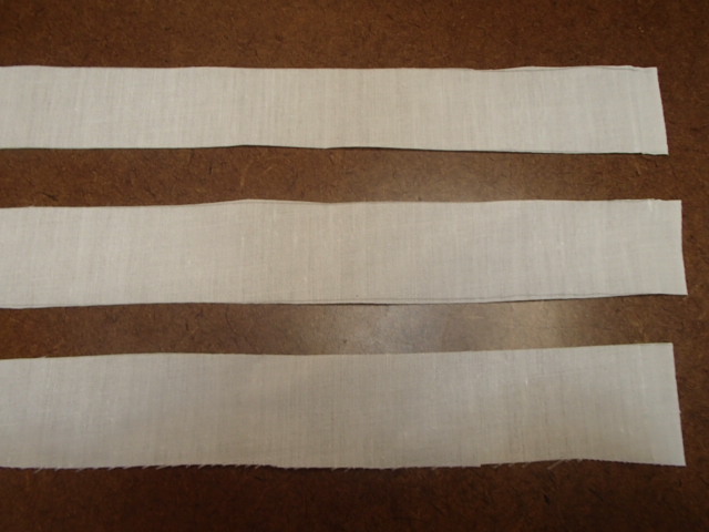
Finally, cut 3 pieces of 1in by 17 inches out of the lightweight cotton. This will be used to create a casing for the LED strip lights.
All these pieces will make one leg warmer; therefore, make sure to cut double the amount because we have two legs!!!
The lining
Making the lining is the first step because it will be what we are attaching our LED’s to. First, sew the two lining pieces together using the seam that had a 1-inch seam allowance. This is where we will be inserting the zipper, so we have easy access to our LEDs in the future if anything needs to be fixed.
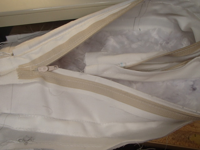
Inserting the Zipper

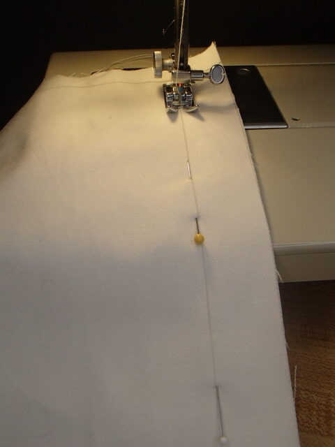
Mark on the fabric where the beginning and end of the zipper will be. This way, you can have a normal stitch where the zipper will not be, a backstitch at the beginning and end of the zipper, and basting for the zipper’s opening.
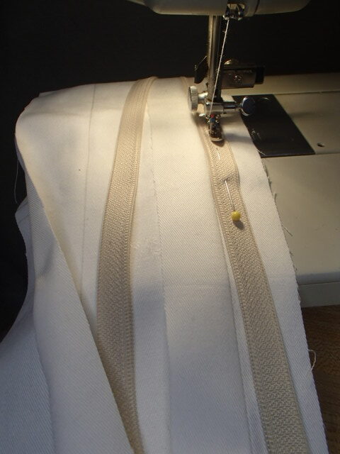
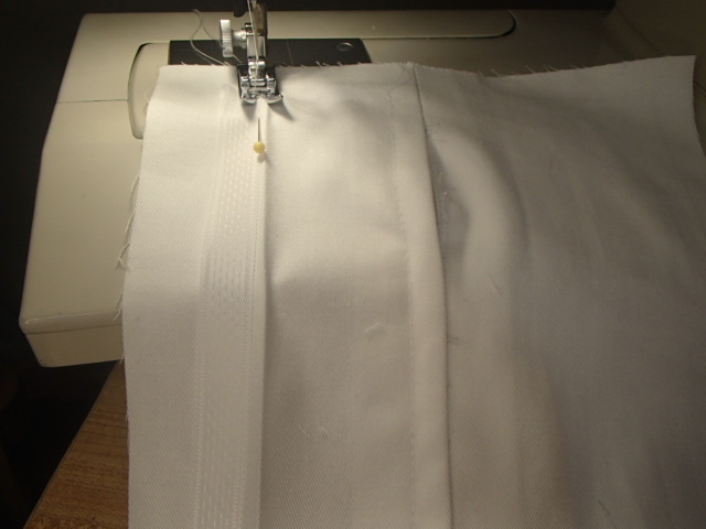
Insert your zipper. Lapped zippers are my favorite, so that is how I will be inserting my zipper. Iron open the seam. Line up the zipper teeth with the seam on the lower of the two pieces. You will know it is the lower because it has the half-inch seam allowance, not the 1.5.
Flip the zipper and seam allowance to sew the second seam through two seam allowance layers and the zipper tap. This will create the small tuck that easily makes the lapped zipper never seen.
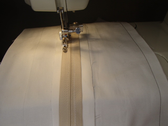
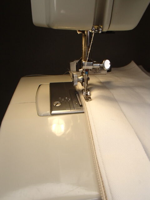
Finally, lay the seam flat and stitch the second since of the zipper down. Starting at the zipper base, sew the small leg of the lapped seam turning 90 degrees and continuing the stitch parallel to the seam.

Seam rip open the basting stitches and your zipper is completed.
Creating the Circuit
Prepping the hardware
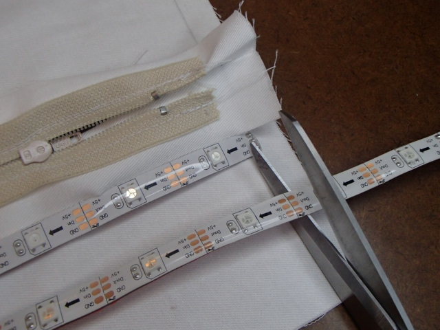
Cut the LED’s to the length so that the entire strip will be withing the stitching lines. For my design, I cut the strips into 13 LED’s each.
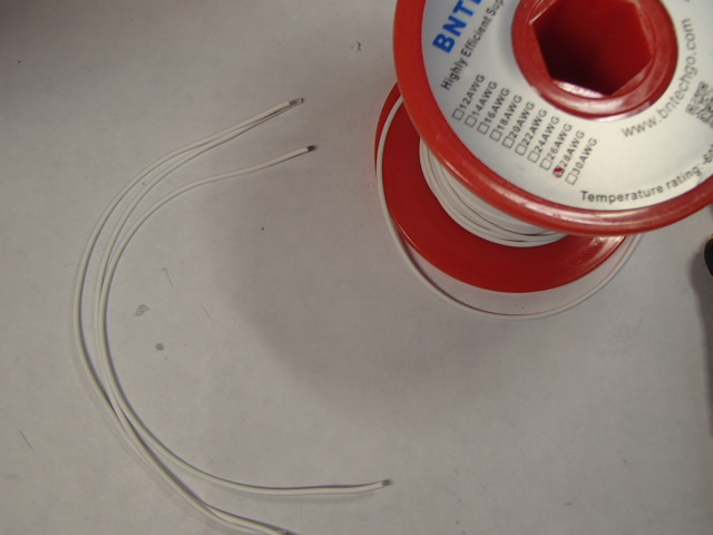
Next, cut the wire into pieces that are about 4 inches long. Strip the coating off, so they are ready to solder. Attach the wire to the solder points of the strip. Make sure that you are soldering the data-in side. Since you are soldering a wire to a flat solder point, tin both the wire and the solder point. This will make it easier to adhere to each other.

Now it is time to solder the ports that will be used off of the board. I know I will be using VCC, GRD, 2, 3, 4, and 6. If you don’t know, wait and work out the ports on the Arduino board.
Breadboarding the Circuit

Time to breadboard the circuit. This is a great way to ensure that all solder points are good and everything is working before it is inserted into the garment.
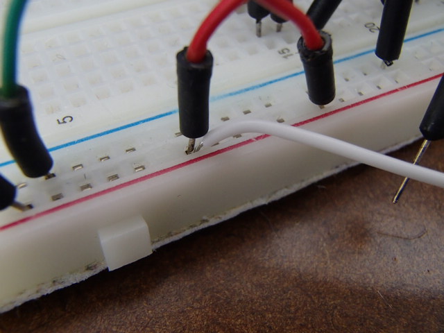
I sometimes find that the wires pull out easily when I am trying to complete the circuit. I will sometimes use the jumper cables to make sure that the wires stay in place.

Now that I have the breadboard set up and it is time to test that everything will light up, it is time to insert some code. I chose a pre-completed code that I had used before, and I knew it would prove my LED’s and circuit wiring test. It is called buttoncycler.
Inserting the code

Since this is the first time I am using the Seeduino I had to download the matching board manager boards. Once I had the board connected, I could easily upload the program to the board.
I can see that the code is good, and all my solder points are solid.
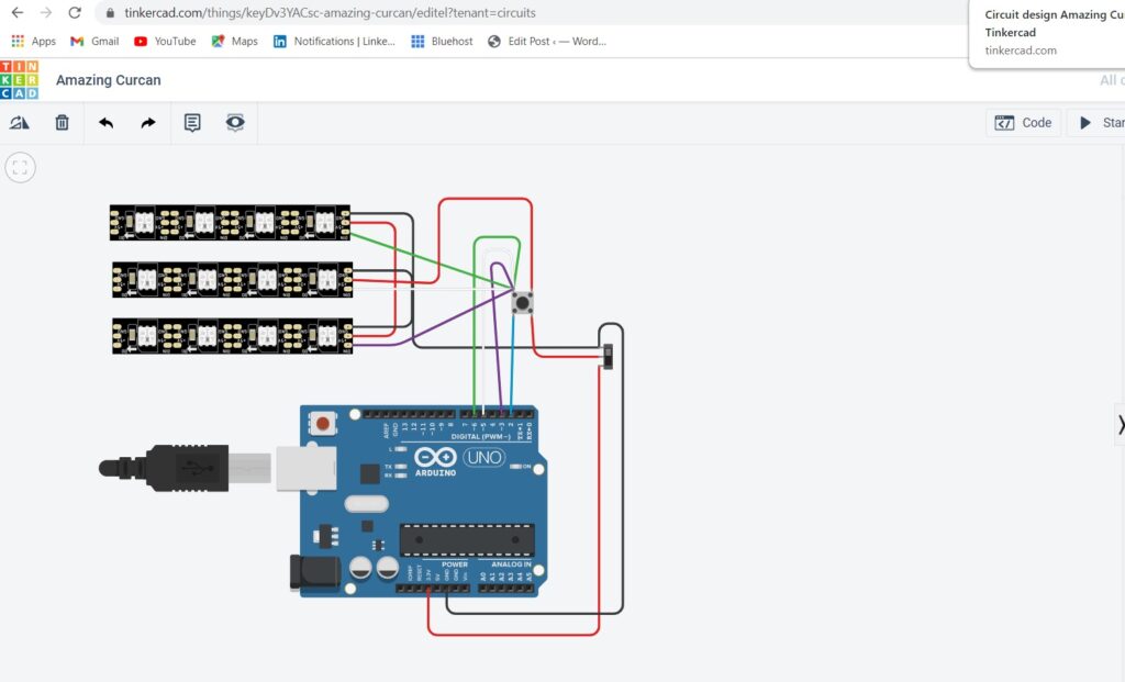
I created a TinkerCAD design to help organize my circuit for soldering.
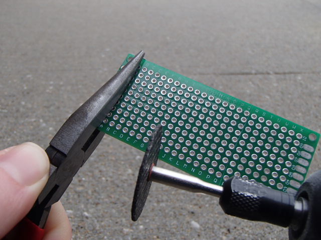
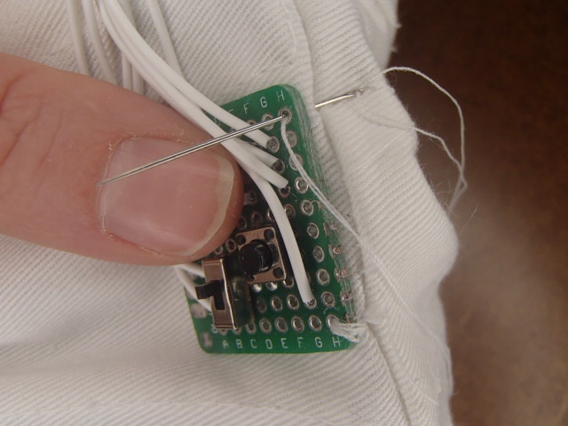
Next, I cut my PCB board to size so the button, switch, and wires can easily be attached to create the circuit.
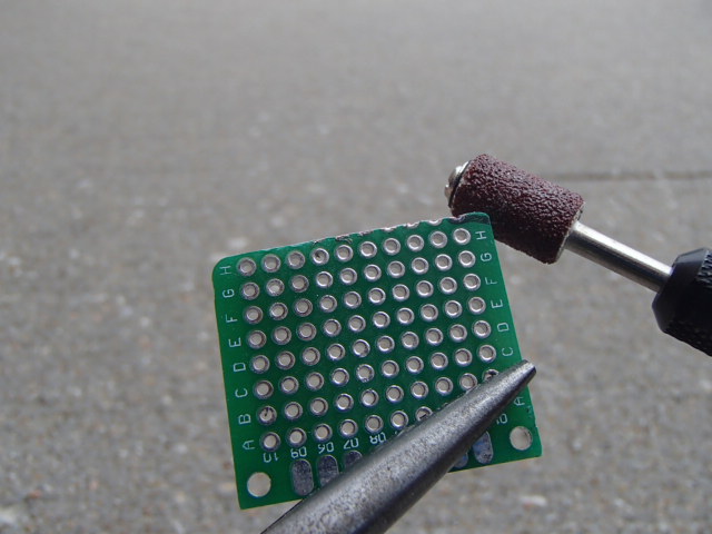
It is also important to sand the cut edge and sand the corners so that there is nothing sharp in the garment.
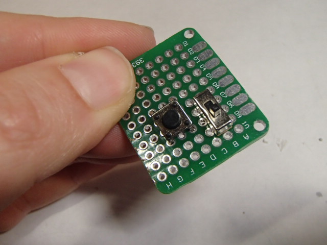
Place the Switch and button onto the PCB board. Since I know that the center prog of the switch will be lined up with one of the prongs of the button, I match the two points up so they can be quickly soldered together.

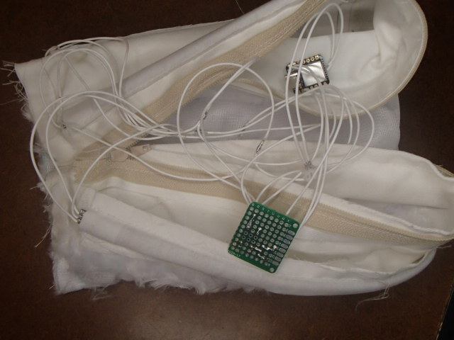
Now using my diagram as a guide, I solder all wires to the PCB board.

To help with the numbers of wires being attached to the PCB board, I connected all the LEDs’ positive wires to a single wire that would travel to the PCB board. I did the same with the Negatives.
It is now time to put the LED’s into the Light-up Leg Warmers
Attaching the LED’s to the Programmable Light-up Leg Warmers
We want to create a casing for the elastic to be inserted into. This will help hold the Leg Warmer on your leg while you are dancing around!!! Use a .5 inch bias and topstitch on the top and bottom, lining the top up with the top stitch line.
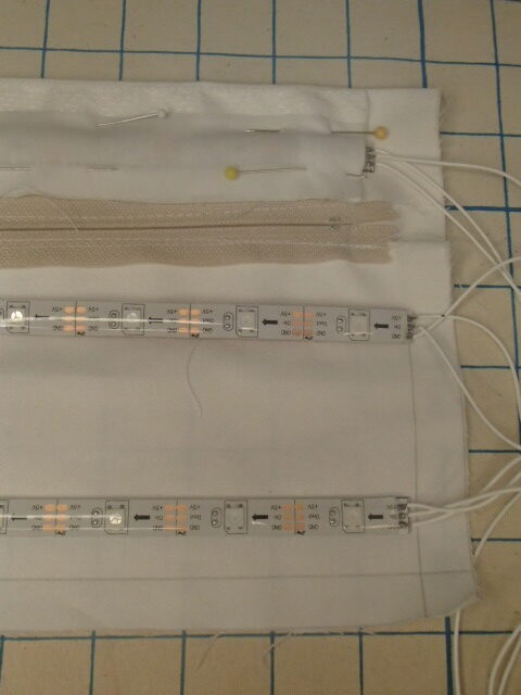
Time to add the LED’s onto the lining. Using the lightweight cotton, place the LED strips on the inside of the lining. I designed mine to be located .5 inches down from the top, directly below the zipper, and .5 up from the hem.
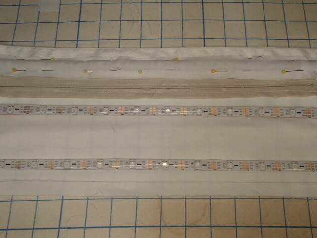
To make sure that the LED’s were not having to shine through more layers than necessary I added the extra Long seam allowance at the top. The top strip will be attached to the seam allowance.
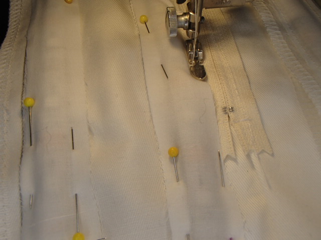
Now that the LED’s are placed, lay the lightweight cotton over the top and pin down either side. This will create the casing holding the LED’s exactly where they were designed.
Creating the Programmable Light-up Leg Warmers
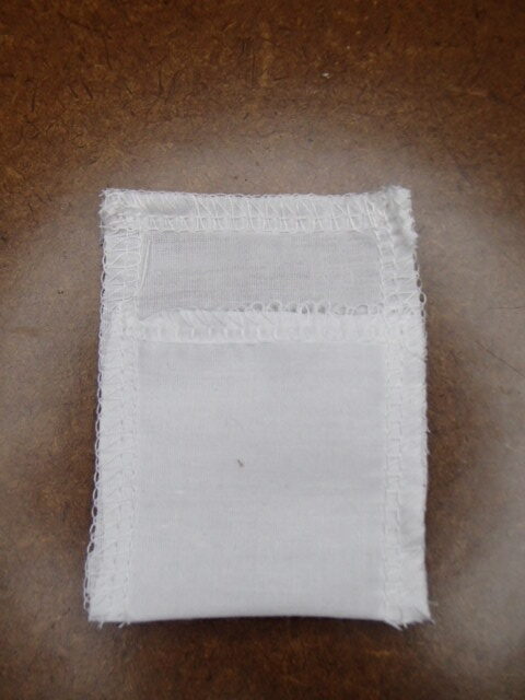
Time to add a pocket for the battery. Using a rectangle of scrap serge on the short side. Fold the rectangle up so that the battery can easily fit inside—Serge around the other three edges.

Attach the Battery pocket to the flap of seam allowance near the opening of the zipper.
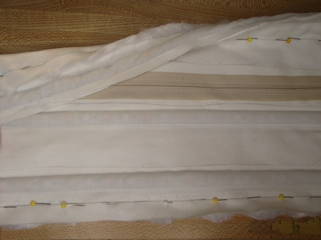
Next, we are going to sew the fur to the lining along the two long sides. Line up the stitch lines and sew. Make sure the zipper is partially open, so it is easier to finish opening it later.
Complete the Programmable Light-up Leg Warmers
Time to make the rectangle a cylindrical piece. Take one short in and begin flipping it to the insides so that the right sides are facing together.

Bring it to the other end and line up the seam. Make sure that there is no twist in the fabric, or it will need to be resewn.
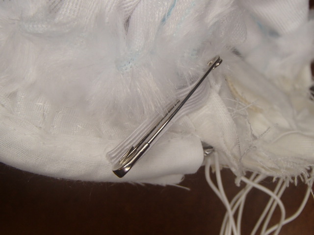
Before flipping right side out, feed your elastic through the casting. I used a 14 inch elastic. For now, I safety pinned the two ends together in case I want to tighten or loose after trying on the leg warmer.
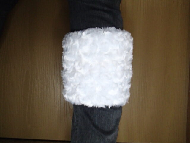
Now the leg warmer is folded in half and the seams are lined up, we can sew it into a cylinder. Pulling through the zipper opening, turn the Leg Warmer so that it is right side out.
Leg warmer filpped right side out.
Final touches
Attach the PCB board with the button and switch to the center back bottom. This way, you will reach the button to switch the code if you choose to. The on/off switch will also e easily accessible.

Help control the wires by whipstitching around them to create a thread casing.
Try on your Leg warmer, and if the elastic is tight enough, machine the two ends together.
Zip closed the lining put on some dancing boots with your legwarmers, and start showing off your new Programmable Light-up Leg Warmers!!!
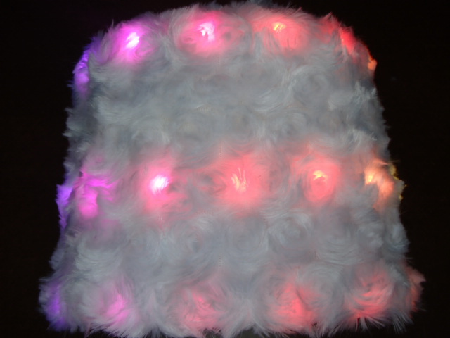
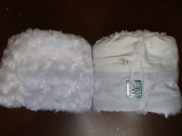
Final Pictures of the Programmable Light-up Leg Warmers


I hope you love dancing around in your Light-up leg warmers. Did you miss yesterday’s post? Make sure to check out the Light-up Santa Ornament. Come back tomorrow for Day 24!!!
Want a Checklist to start your own Wearable Technology Toolkit?
